
Segment Routing: Explicit Traffic Engineering Policies (SR-TE)

We have a shiny new Segment-Routing MPLS core, and one of the many available features this brings is enhanced Traffic Engineering. Here we will run through one such example implementation of a SR Traffic Engineering (SR-TE) policy…
Overview
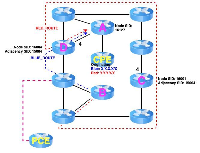
We have the below example topology, in which a CPE device is announcing two prefixes to us, X.X.X.X/X and Y.Y.Y.Y/Y:
 -
-
As you can see, we will be “colouring” the two prefixes, Red and Blue, with traffic engineering policies to ensure that all traffic from Router B to each prefix takes diverse routing paths through the network.
Blue will route explicitly to Router D, and then route out of an explicitly defined interface to Router A. Red, however, will route explicitly to Router C, and will then route out of an explicitly defined interface towards Router A.
In order to structure these explicit routing instructions, we use Segment IDs (SIDs). We have two types of SID defined in the above topology:
- Node-SID: Globally unique, specific to an SR device
- Adjacency-SID: Locally unique, specific to a SR interface
Configuration
Our PCE has it’s address defined, as well as a password configured that PCE Clients must authenticate with:
configure terminal
 pce
  address ipv4 <PCE Address>
  password <Password>
And other Segment Routing hosts likewise have an association to the PCE configured:
configure terminal
 segment-routing
   pcc
    pce address ipv4 <PCE Address>
     precedence 1
     password <Password>
End routers A and B will need to be configured with the PCE address, and must have the extended communities present that translate to the policies we will be configuring:
configure terminal
 extcommunity-set opaque RED
   1
 end-set
 extcommunity-set opaque RED
  2
 end-set
Likewise, the mid-path routers C and D must have the necessary local Adjacency-SIDs configured on the associated interfaces in your IGP, ISIS in our case:
configure terminal
 router isis <Process Tag>
  interface <SR interface>
   address-family ipv4 unicast
    adjacency-sid index 4
    commit
Now we can create and push the traffic engineering policies on the Segment Routing Policy Control Engine (SR-PCE). We will create the segment-lists with the label path that traffic must follow:
configure terminal
 pce
  segment-routing
   traffic-eng
    segment-list name RED_ROUTE
     index 10 mpls label 16101 !Router C Node-SID
     index 20 mpls label 15004 !Router C Adjacency-SID
     index 30 mpls label 16127 !Router A Node-SID
    segment-list name BLUE_ROUTE
     index 10 mpls label 16104 !Router D Node-SID
     index 20 mpls label 15004 !Router D Adjacency-SID
     index 30 mpls label 16127 !Router A Node-SID
In the Segment-List, you will see that we are stipulating the first label hop as a Node-SID, then the Adjacency-SID of the interface on that device that the traffic must route through. We can then declare the end-device Node-SID as the last hop in the path.
Next, we will need to configure the Traffic Engineering Peer for Router B, and the associated policies. Configure the below on the PCE:
pce
 segment-routing
  traffic-eng
   peer ipv4 <Router B Address>
    policy RED
     color 1 end-point ipv4 <Router A Address>
     candidate-paths
      preference 100
       explicit segment-list RED_ROUTE
    policy BLUE
     color 2 end-point ipv4 <Router A Address>
     candidate-paths
      preference 100
       explicit segment-list BLUE_ROUTE
We are now ready to configure the CPE. Build the necessary route-policies for colouring the prefixes:
configure terminal

prefix-set BLUE
  X.X.X.X/X
end-set

prefix-set RED
  Y.Y.Y.Y/Y
end-set

extcommunity-set opaque RED
  1
end-set

extcommunity-set opaque BLUE
  2
end-set

route-policy COLOURING
  if destination in RED then
    set extcommunity color RED
  elseif destination in BLUE then
    set extcommunity color BLUE
  else
    pass
  endif
end-policy
And we can now bring up the BGP session from the CPE to Router A. On the CPE, apply the COLOURING route-policy outbound:
router bgp <CPE AS>
 address-family ipv4 unicast
  network X.X.X.X/X
  network Y.Y.Y.Y/Y
 neighbor <Router A Address>
  remote-as <Remote AS>
  address-family ipv4 unicast
   route-policy COLOURING out
   send-extended-community-ebgp
And Router A, to complete the BGP session establishment:
router bgp <Local AS>
 neighbor <CPE Address>
  remote-as <CPE AS>
We are now done configuring!
Verification
We can see that the BGP session is now established:
RP/0/RSP0/CPU0:Router-A#show bgp neighbor <CPE Address>
Fri Dec  7 17:48:51.058 GMT

BGP neighbor is <CPE Address>
 Remote AS <CPE AS>, local AS <Local AS>, external link
 Remote router ID <CPE Address>
  BGP state = Established, up for 00:00:05
And we are receiving our prefixes:
Status codes: s suppressed, d damped, h history, * valid, > best
              i - internal, r RIB-failure, S stale, N Nexthop-discard
Origin codes: i - IGP, e - EGP, ? - incomplete
   Network     Next Hop    Metric  LocPrf Weight Path
*> X.X.X.X/X  <CPE Address>   0        0 <Local AS> <CPE AS> i
*> Y.Y.Y.Y/Y  <CPE Address>   0        0 <Local AS> <CPE AS> i
Looking on Router B, we can see the the PCE has pushed the newly created policies:
RP/0/RSP0/CPU0:Router-B#show segment-routing traffic-eng policy

SR-TE policy database
---------------------

Color: 1, End-point: <Router A Address>
  Name: srte_c_1_ep_<Router A Address>
  Status:
    Admin: up  Operational: down for 00:02:56
  Candidate-paths:
    Preference: 100 (PCEP)
      Name: RED
      Requested BSID: dynamic
      PCC info:
        Symbolic name: RED
        PLSP-ID: 1
      Dynamic (pce <PCE Address>) (valid)
        Metric Type: TE,   Path Accumulated Metric: 0
          16001 [Prefix-SID, <Router C Address>]
          15004 [Adjacency-SID, <Router C Address>]
          16004 [Prefix-SID, <Router D Address>]
  Attributes:
    Forward Class: 0
    Steering BGP disabled: no
    IPv6 caps enable: no

Color: 2, End-point: <Router A Address>
  Name: srte_c_2_ep_<Router A Address>
  Status:
    Admin: up  Operational: down for 00:02:56
  Candidate-paths:
    Preference: 100 (PCEP)
      Name: BLUE
      Requested BSID: dynamic
      PCC info:
        Symbolic name: BLUE
        PLSP-ID: 2
      Dynamic (pce <PCE Address>) (valid)
        Metric Type: TE,   Path Accumulated Metric: 0
          16004 [Prefix-SID, <Router D Address>]
  Attributes:
    Forward Class: 0
    Steering BGP disabled: no
    IPv6 caps enable: no
And a traceroute from Router B to each prefix shows we are correctly routing along the corresponding engineered path:
RP/0/RSP0/CPU0:Router-B#traceroute X.X.X.X

Tracing the route to X.X.X.X

2  <Router D Address>                      3 msec  *  3 msec
3  <CPE Address>                           5 msec  *  5 msec

RP/0/RSP0/CPU0:Router-B#traceroute Y.Y.Y.Y

Tracing the route to Y.Y.Y.Y

3  <Router C Address>                      4 msec  *  4 msec
7  <Router D Address>                      11 msec * 11 msec
8  <CPE Address>                           13 msec * 13 msec
Success, routing to our two prefixes are each taking their respective explicit paths!
This has been a quick run through of an example implementation of Segment Routing Traffic Engineering. I will be continuing to study and test these technologies and use-cases as we progress with phasing in Segment Routing into our MPLS Core.
Thanks for reading!